
Each week I get an Exponential View newsletter (which I highly recommend) and in it is always a reminder about the CO2 levels in the atmosphere. At some point, I realized that those ppm numbers don’t mean much to me. I wanted to know how CO2 affects me and what can I do about it. It was time for a little bit of research.
Carbon dioxide (CO2) levels in the atmosphere are rising like never before. Just 50 years ago, atmospheric CO2 was at 326 parts per million. 25 years ago it was 360 ppm. A few months ago, it reached 415 ppm. This is based on the measurements from the Mauna Loa Observatory, which is continuously monitoring the levels since 1958.

If this trend continues, in the next few decades, the earth’s temperature will rise, ecosystems will be damaged, food quality will decrease or to put it simply – our planet would not be a nice place to live.
I stumbled upon a recent study performed in my country, about indoor air quality in schools and the effects of high CO2 concentrations. Monitoring was performed in five primary schools during the heating season. Obtained results show that the average values of CO2 concentration during classroom occupancy mainly exceed 1000 ppm and in some classrooms even 1500 ppm, which indicates inadequate ventilation.
Many studies suggest that high indoor CO2 levels may cause occupants to grow drowsy, to get headaches, or to function at lower activity levels. The concentration of 1000 ppm seems to be a threshold when people start to complain about air quality.
If we take all of the above – rising CO2 levels in the atmosphere will lead to higher CO2 levels in our homes, and opening the windows may not help us in the future.
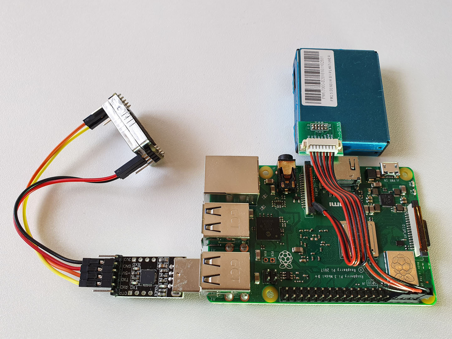
I have already built a device for monitoring the indoor air quality with particulate matter, temperature, humidity, and pressure sensors. Armed with new knowledge about the CO2, my next goal was to add a CO2 sensor.
In the following lines, you can learn how you can build a CO2 monitor for yourself.
Hardware
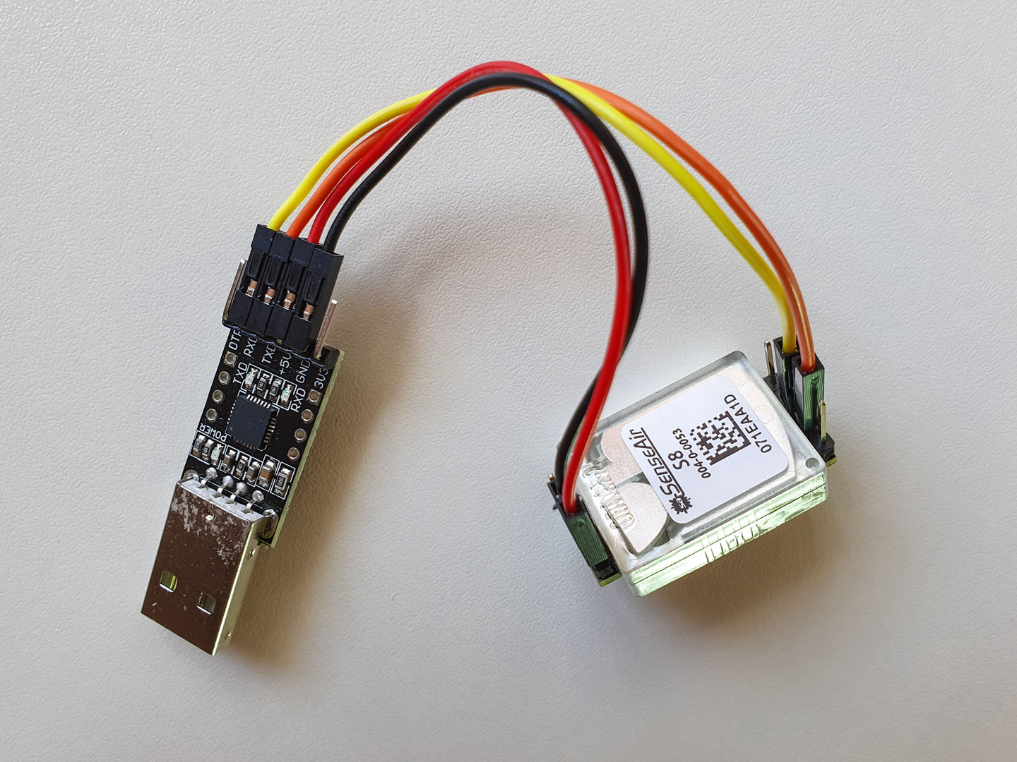
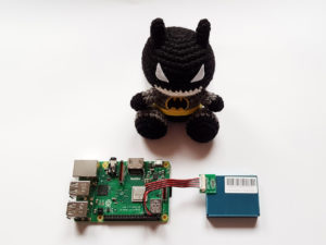
After sharing my article about indoor air quality on Hacker News, I got a lot of great responses. A discussion about CO2 sensors led me to decide to get a Senseair S8 as a good and low-cost solution for indoor usage. It’s factory calibrated and seems to be very accurate. I got it from AliExpress, with welding pins.
Since I wanted to connect it to a Raspberry Pi and I already used the GPIO pins for connecting a PMS7003 sensor – I also bought a USB to UART adapter.
You’ll also need 4 female-to-female “dupont” cables, to connect the sensor and the adapter.
Handle the sensor with care and avoid touching the particle filter.
Always wash your hands first to avoid the risk of static electricity, hold the circuit boards by its edge and don’t touch the components.
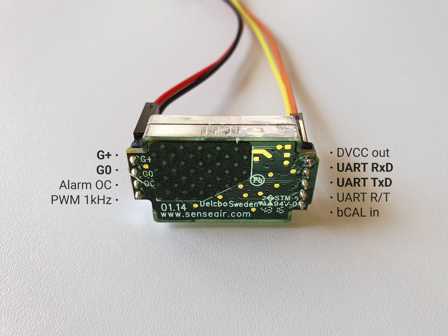
Connect the sensor and the adapter pins according to the following table:
| USB-UART adapter | Senseair S8 |
| 5V | G+ |
| GND | G0 |
| RXD | UART TXD |
| TXD | UART RXD |
Checkout the Senseair S8 specification for the description of pin functions. For our case, we will use only power supply plus and minus (ground) pins and UART data input and output pins.
Software
Setup
As in previous articles, I’m using Java. Since the Senseair sensor is using serial communication, we’ll need a library for serial port access. I used Pi4J before, but Pi4J seems not to support a case when you want to use multiple serial devices, so I switched to jSerialComm.
Start by including the jSerialComm dependency in your project:
	com.fazecast
	jSerialComm
	2.5.2
To find out the descriptor of the serial port you are using for the sensor, use the command dmesg | grep tty. In the result list you should see something like this:
[1393740.530266] usb 1-1.2: cp210x converter now attached to ttyUSB0This means that the port is /dev/ttyUSB0.
Protocol
Senseair S8 uses a Modbus protocol. The protocol implementation is described in the official document, with all of the details.
Here we only need to send a read command (0xFE 0x44 0x00 0x08 0x02 0x9F 0x25) to get a CO2 measurement and read the result (a sequence of 7 bytes).
Java code
In the following lines, we configure the serial port access, write the bytes of the read command and then read the response, which is a current measurement of CO2 in ppm.
@Slf4j
public class SenseairS8Driver {

	private static final byte[] READ_COMMAND = {
			(byte) 0xFE,
			(byte) 0x44,
			(byte) 0x00,
			(byte) 0x08,
			(byte) 0x02,
			(byte) 0x9F,
			(byte) 0x25 };

	public Integer measure() {
		SerialPort port = SerialPort.getCommPort("/dev/ttyUSB0");

		if (!port.openPort()) {
			log.warn("Failed to open port.");
			return null;
		}

		port.setComPortTimeouts(
				SerialPort.TIMEOUT_READ_BLOCKING | SerialPort.TIMEOUT_WRITE_BLOCKING,
				500,
				500);

		port.setComPortParameters(9600, 8, SerialPort.ONE_STOP_BIT, SerialPort.NO_PARITY);
		port.setFlowControl(SerialPort.FLOW_CONTROL_DISABLED);

		Integer value = null;

		try {
			if (port.writeBytes(READ_COMMAND, READ_COMMAND.length) != READ_COMMAND.length) {
				log.warn("Failed to write bytes.");
				return null;
			}

			byte[] responseBytes = new byte[7];

			if (port.readBytes(responseBytes, 7) == 7)
				value = (Byte.toUnsignedInt(responseBytes[3]) << 8) + (Byte.toUnsignedInt(responseBytes[4]));
			else
				log.warn("Failed to read bytes.");
		}
		finally {
			if (!port.closePort())
				log.warn("Failed to close port.");
		}

		return value;
	}

}
Now let’s schedule a task to print a measurement every minute:
@Slf4j
public class SenseairS8Manager {

	public static void main(String[] args) {
		SenseairS8Driver driver = new SenseairS8Driver();

		ScheduledFuture future = Executors.newSingleThreadScheduledExecutor()
				.scheduleAtFixedRate(
						() -> log.info("CO2: {} ppm", driver.measure()),
						0L,
						1L,
						TimeUnit.MINUTES);

		Runtime.getRuntime().addShutdownHook(new Thread(() -> {
			if (!future.isDone())
				future.cancel(true);
		}));
	}

}
Next steps and ideas
- Write code to send you a message to your favourite messenger app when the CO2 concentration in your home is too high, to remind you to open the windows.
- Store the measurements in InfluxDB and use the data to create graphs
- Learn more about the CO2:

3 comments
Hello,
Thanks for sharing your work, I’ll use the same sensor on a Raspberry Pi, did you manage to find a way to show the data in a more user friendly way ? For example, a graph with the current Co2 level on a webpage or a gui window displayed on an attached screen.
Hi. Why do you use modbus command 0x44? Register number 0x0008? I didn’t find any informations about this command and addresses in the attached documentation. Do you have some other documentation? How to read the temperature?
Actually I never consulted the provided documentation, because I somewhere found a working example of the command that can be used to read the CO2 value. Maybe the linked documentation is not for this version of the sensor?
The following sequence of bytes form a command used to read the RAM: